
s.o.l. meter
Meter Design
|
|
www.igglybob.com s.o.l. meter Meter Design |
|
the main - main page - about me - l.o.u.n.g.e. - r.e.t.a.r.d. - s.o.l. meter - s.c.r.e.a.m. - videos the l.o.u.n.g.e. - overview - 2006 edition - 2007 edition - 2008 edition - control the s.c.r.e.a.m. - main page - tech review - proposal - draft summary the r.e.t.a.r.d. - overview - assignment - proposal - requirements - timeline - the core the s.o.l. meter - overview - car modification - meter design - meter input |
I. Design Objectives The s.o.l. meter will display its output in an 11-digit seven-segment LED display (0.000000000c). The last of these digits will always read "c", to indicate that the speed is a factor of the speed of light. The first seven-segment LED will always display a zero and the decimal point. The other nine will be determined by the speed at which the vehicle is moving (or, more specifically, the voltage across the speedometer). Other design objectives include: - Critical damping, in a digital sense - Small size - Inexpensive parts - Infinite (or extremely high) input impedance Of these objectives, input impedance is the most important. If the input impedance of the s.o.l. meter is too low, the amount of current traveling through the device will affect the speedometer, causing it to read values lower than the actual value. While this would provide an excellent excuse against speeding tickets, it is unlikely that an officer of the law would respect this. II. Display Design The first aspect of designing the s.o.l. meter display was to determine how many digits actually needed to be displayed. The value 0.000010000c corresponds to 1864.1 mph, which is certainly an attainable speed in the chosen vehicle, though the likelihood of travel at this speed is, admittedly, very small. Therefore, a maximum speed of 0.000009999c can be reasonably established, giving a maximum readable speed of 1863.927 mph. This also means that the meter can detect changes in speed as small as 0.000000001c, or 0.1864 mph. When one considers that a possible application of this meter can be to detect time dilation (according to Einstein's Special Relativity [1]), one can detect changes in the length of time as small as 10^-16 percent; that is, 0.0000000000000001%. Without a meter this sensitive, punctuality cannot be ensured. Since only four digits on the meter are being manipulated, the ICL7135 [2] was chosen as a suitable analog-to-digital converter. The ICL7135 gives BCD (binary-coded decimal [3]) output, which is a necessity for this application, since converting from hexadecimal to BCD would be prohibitively expensive in terms of both space and money. The cost of the ICL7135 was minimal ($3.88) and its sensitivity much greater than other 8-bit alternatives. The ICL7135 is a "4 and 1/2 digit" converter, meaning that the range of values it supports is approximately 20000, which is approximately equivalent to a 14-bit converter. However, due to the meter contraints defined earlier, only four digits will be used, meaning that the range of values is 10000. For the actual seven-segment display pieces, a generic red 0.39" model was chosen [4]. It was hoped that the red display would match the existing red display of the car relatively well. III. Power Supply The BMW 318ti has one source of power (+12 VDC) and a ground which can be easily tapped. This is unfortunate, as the ICL7135 also requires a -5 VDC power source. However, several workarounds can be used. The particular workaround chosen here utilizes a 9 volt battery, a 7805 (+5V regulator), and a 7905 (-5V regulator). Figure 1 shows a schematic of this design. The author believes it to be an ugly hack of a solution; however, it is small, uses few components, and is suitable for this particular project. Therefore, it was chosen. 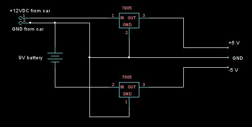 Figure 1. Hack power supply providing +5V, GND, and -5V. IV. Connecting the Pieces The last piece required was a clock for the ICL7135. Through various methods, such as digging through boxes, torching old ISA cards, and asking acquaintances, a 4.8364 MHz clock was found. However, its original source remains unknown as it arbitrarily appeared on the workbench one day. Unfortunately, 4.8364 MHz is still too fast for the ICL7135, so a 7490 chip was used to divide the clock by a factor of 10 (resulting in a final clock speed of 483.64 KHz, which is much more acceptable). With this problem solved, the only thing left to do was to put everything together. Details are irrelevant as one can simply see the schematic in Figure 2 (click to enlarge). Figures 3 and 4 show the prototype, built on a breadboard. Readers should note that the NPN transistor powering the second seven-segment LCD is dying; this explains why the light given by the second LCD is less bright. 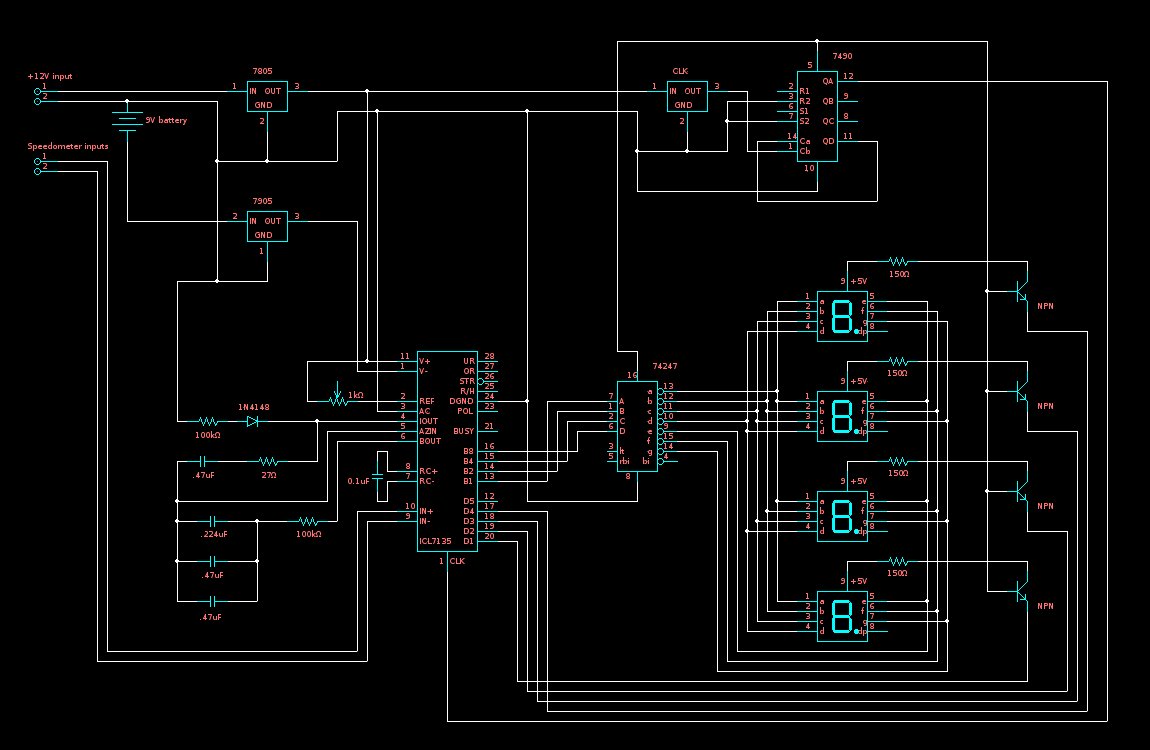 Figure 2. Prototype schematic for the s.o.l. meter. 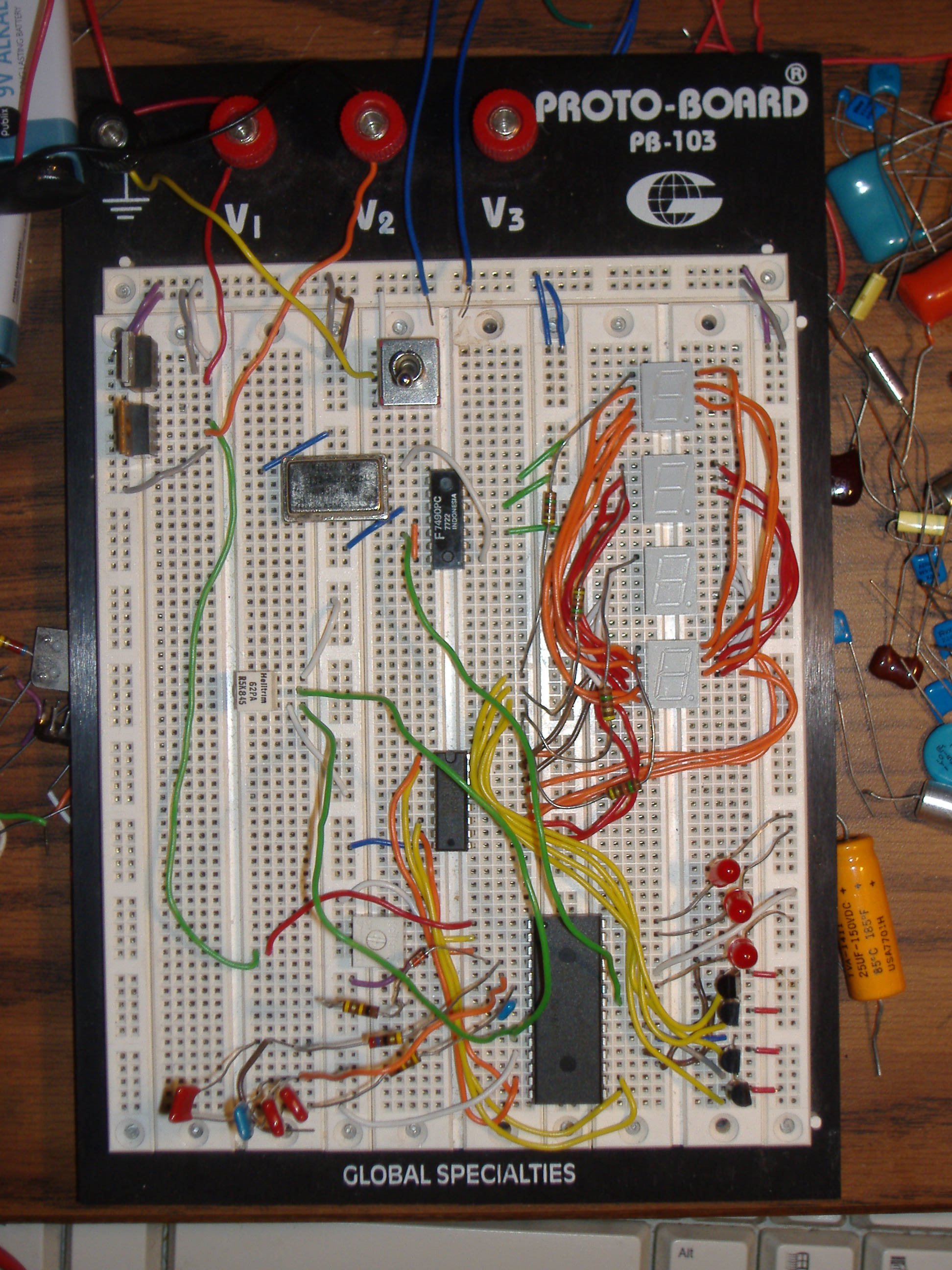 Figure 3. The s.o.l. meter prototype on a breadboard. 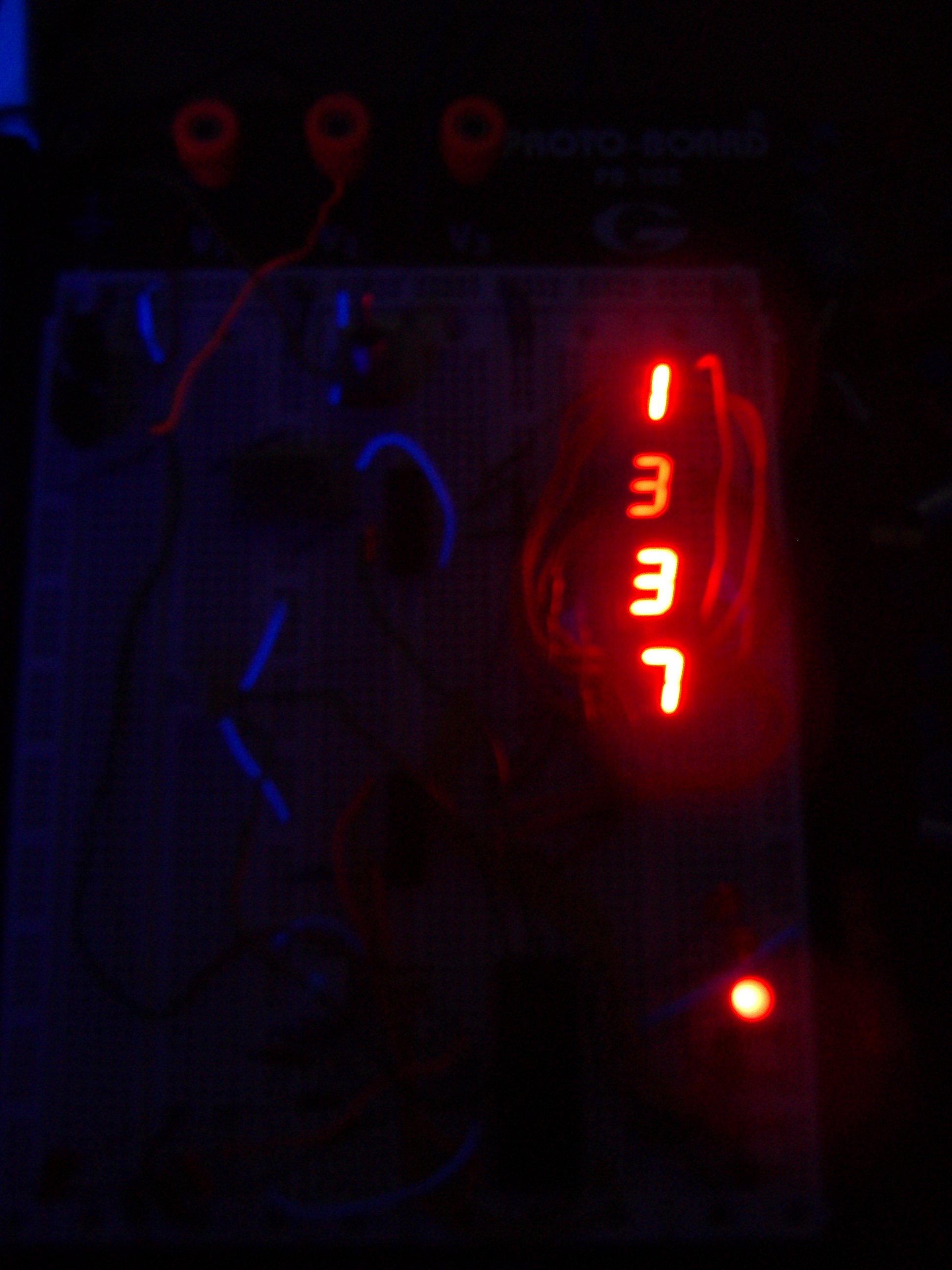 Figure 4. The s.o.l. meter prototype, functioning. Upon the design of the s.o.l. meter (a schematic of which can be seen in Figure 2), it was discovered that the speed-to-voltage curve of the speedometer inputs was nonlinear, but instead parabolic. As it was assumed that the curve would be linear, this presents a large problem, in that the speedometer inputs will need to be filtered and modified to create a linear voltage curve. More information can be found at the speedometer input page [5]. VI. Summary of Required Parts Given below is a list of the parts (excluding wires) used to assemble the s.o.l. meter prototype. It should be noted that the assembled prototype relies on a 9 volt battery instead of a 12 volt input from the car (as it is not yet connected to the car), making it use two 9 volt batteries. The list below only enumerates one of these. - one ICL7135 (analog-to-digital converter) - one 7490 (divide-by-ten counter, for the clock) - one 4.8364 MHz clock - one 74247 (BCD-to-seven-segment-display driver) - four NPN transistors - four 0.39" red seven-segment displays - one 1N4148 diode - one 7805 (+5 volt regulator) - one 7905 (-5 volt regulator) - one 9 volt battery - two 100 kiloohm resistors - one 27 ohm resistor - four 150 ohm resistors - one 0.1 microfarad capacitor - three 0.47 microfarad capacitors - one 0.224 microfarad capacitor - one 1 kiloohm potentiometer VII. References [1] http://www.einstein-online.info/en/elementary/specialRT/index.html [2] http://www.igglybob.com/projects/sol_meter/icl7135.pdf [3] http://www.cacs.louisiana.edu/~mgr/404/burks/foldoc/15/12.htm [4] http://www.digikey.com/scripts/DkSearch/dksus.dll?Detail?name=160-1578-5-ND [5] http://www.igglybob.com/projects/sol_meter/speedometer_input.php |