s.o.l. meter
Car Modification
|
|
www.igglybob.com s.o.l. meter Car Modification |
|
the main - main page - about me - l.o.u.n.g.e. - r.e.t.a.r.d. - s.o.l. meter - s.c.r.e.a.m. - videos the l.o.u.n.g.e. - overview - 2006 edition - 2007 edition - 2008 edition - control the s.c.r.e.a.m. - main page - tech review - proposal - draft summary the r.e.t.a.r.d. - overview - assignment - proposal - requirements - timeline - the core the s.o.l. meter - overview - car modification - meter design - meter input |
I. Overview of Objectives and Process The goals of the car modification are straightforward and simple: insert a wire to transmit the voltage across the speedometer itself to the s.o.l. meter. The voltage serves as the input to the s.o.l. meter.
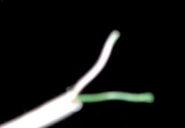
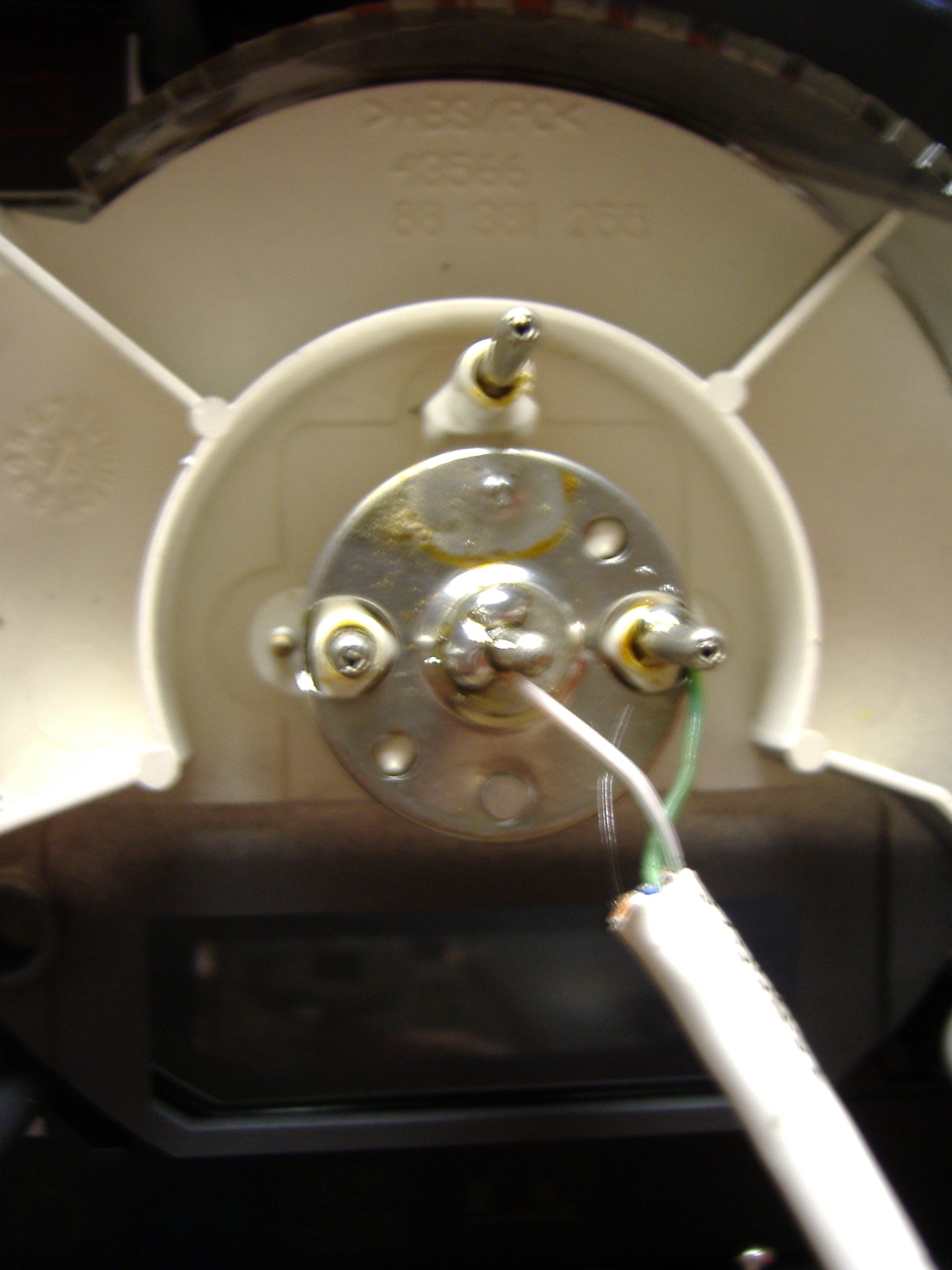
II. Removal and Disassembly of Instrument Cluster Removing the instrument panel from the car was done in eight simple steps: 1. Turn off car. 2. Unscrew instrument cluster's two Torx mounting screws. 3. Pull instrument panel onto steering wheel. 4. Turn car on. 5. Rotate steering wheel one radian clockwise. 6. Disconnect car battery. 7. Disconnect three connectors from back of instrument cluster. 8. Wedge instrument cluster through gap between wheel and center dashboard. Unfortunately, during the actual procedure, the order of the procedure was not followed correctly, resulting in the "actual procedure" taking approximately 74 steps. The removed instrument cluster can be seen in Figures 2 and 3. In Figure 2, it should be noted that the position of the speedometer is not in any way indicative of the normal position of the speedometer. Under regular operation, the speedometer should be deflecting at least 180 degrees further clockwise. Once the instrument cluster was obtained it was brought to a well-lit area. 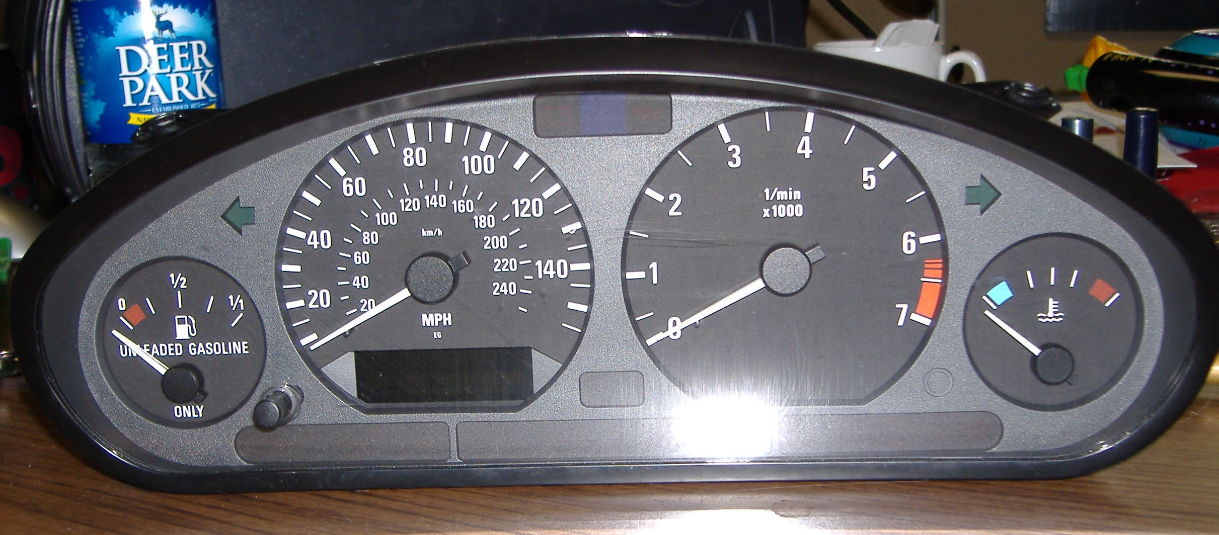 Figure 2. Front view of instrument cluster. 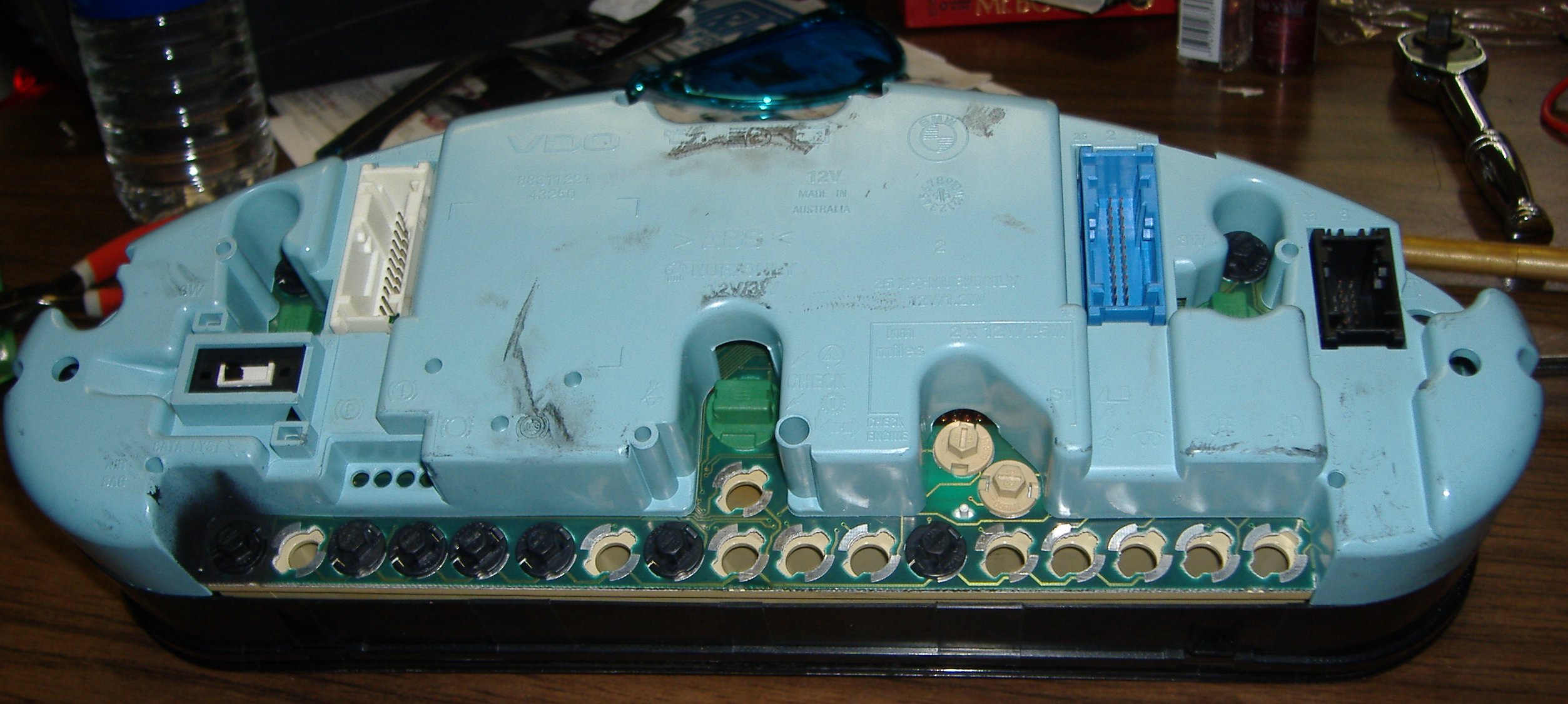 Figure 3. Rear view of instrument cluster. To disassemble the instrument cluster, five Torx screws had to be removed from the perimeter of the back of the cluster. After this, the front and back of the instrument cluster was pulled gently apart into two pieces. At this point, any form of warranty covering the panel was verifiably voided. In Figure 4, the rear side of the front end of the cluster can be seen. The leads of all the analog meters can be seen, and the positive and ground leads of the speedometer are indicated. The speedometer can be assumed to function in the same way as a d'Arsonval meter movement or a variant thereof. A quick explanation of the functioning behind the d'Arsonval meter movement can be found at 'All About Circuits' [1]. When a positive DC current is applied to these two terminals, the meter reading deflects. As the current increases, the meter deflects further. It was determined by observation that the speedometer (and all the meters on the instrument cluster being studied) were overdamped; however, this knowledge is irrelevant to the project at hand. 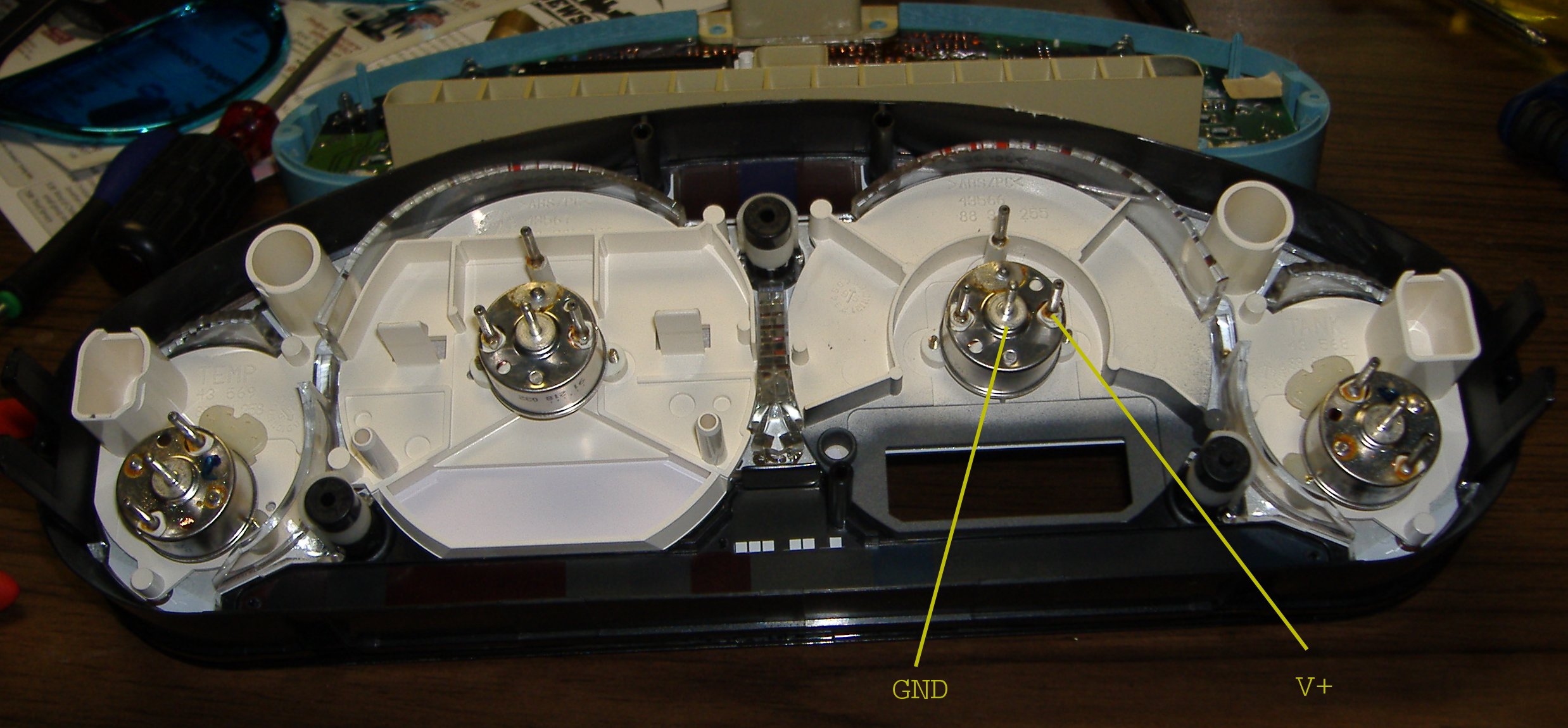 Figure 4. Speedometer leads. III. Modification of Instrument Cluster Once the positive and ground leads of the meter were discovered, the next step was to create a connection to them. To accomplish this, two wires from a CAT5e cable were used. CAT5e was chosen because of its resistance to wear and tear, its shielding, and its flexibility. The cable was cut open at one end and the green and white-green twisted pair were used. The wires can be seen in Figure 5.
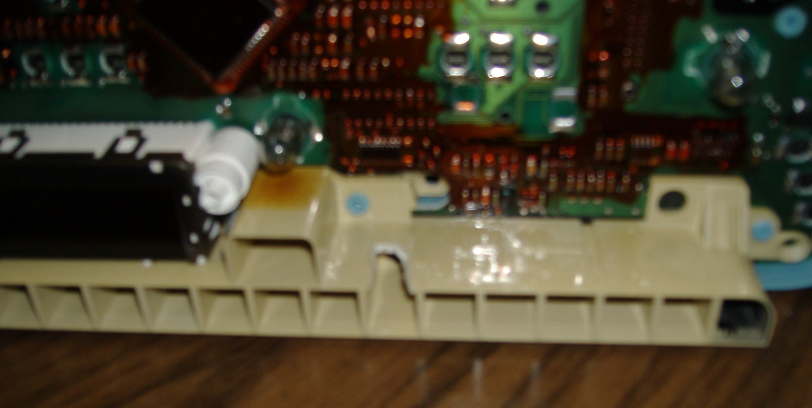 Figure 7. CAT5e pathway through LED casing. Once the CAT5e pathway was created, the CAT5e cable was threaded through it, both pieces of the instrument cluster were put together and secured again. The back side of the reassembled modified instrument cluster can be seen in Figure 8. With this complete, the instrument cluster was reinstalled into the car, following the procedure outlined earlier for removal in backwards order. However, the addition of a CAT5e cable presented a challenge. The cable was threaded through the unused foglight control on the right side of the dashboard and left to dangle for accessibility in making measurements to establish a speed-voltage relationship. The modified dashboard can be seen in Figure 9. 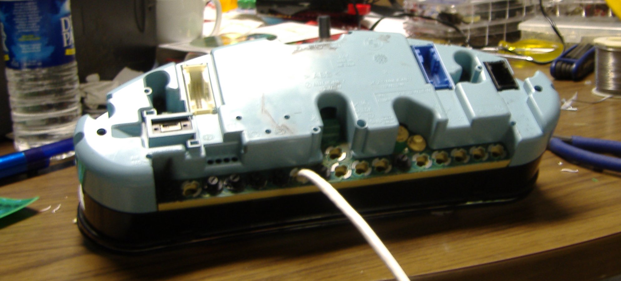 Figure 8. Back side of modified instrument cluster. 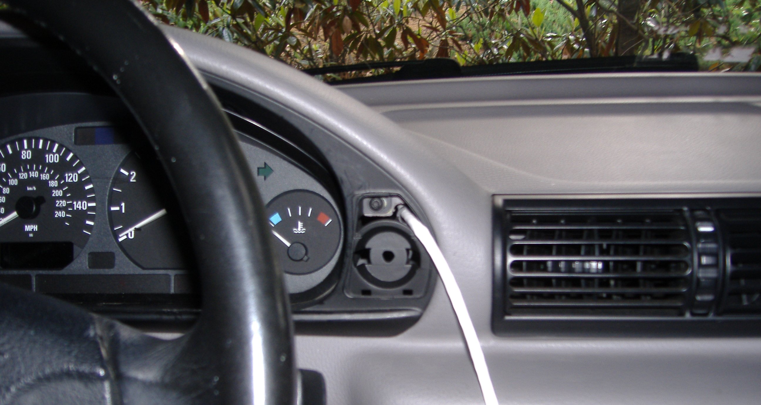 Figure 9. Modified dashboard. V. Inadequacy of Original Modification and Improved Modification After the car modification was complete and the meter assembled, it was discovered that the voltage-to-speed relationship was nonlinear. This presented a large problem, and more on that problem can be found at [1]. Eventually, it was decided that the leftmost lead on the speedometer may contain useful information, so the instrument cluster was removed and disassembled once again. Another wire was soldered to that lead, which can be seen in Figure 10. Then, the instrument cluster was reassembled and reinstalled into the car. 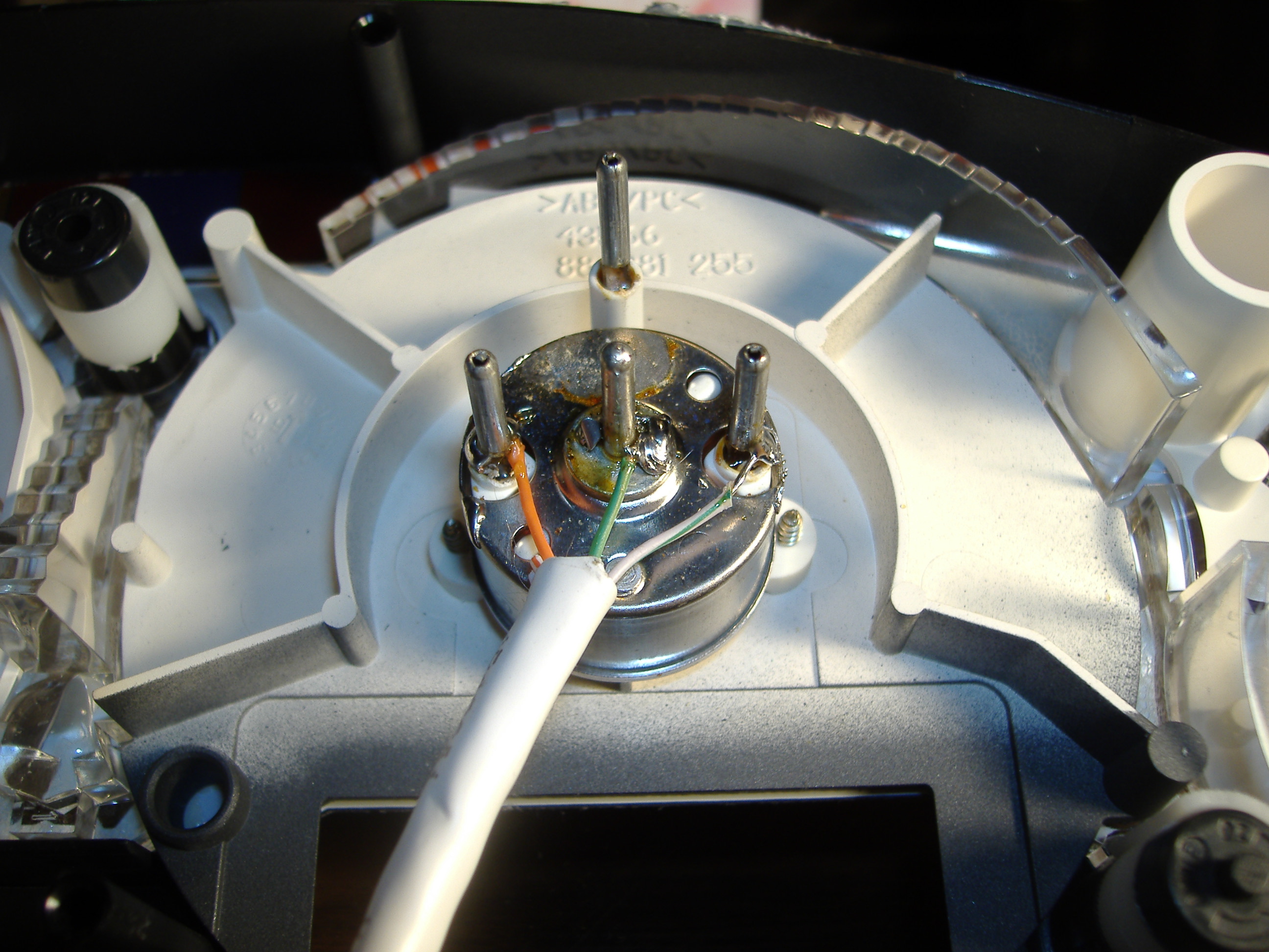 Figure 10. Soldered CAT5e cable with extra lead. VI. References [1] http://www.igglybob.com/projects/sol_meter/speedometer_input.php |