-
-
-
-
-
-
-
-
-
-
-
-
-
-
-
-
-
-
-
-
-
-
-
-
-
-
|
r.e.t.a.r.d.
Real-time Equalizing Transmogrifying Audio Routing Device
Ryan Curtin
05 February 2007
I. Introduction
The Real-time Equalizing Transmogrifying Audio Routing Device (or R.E.T.A.R.D. for short) is a device that aims to make multiplexing between audio devices simple and intuitive. In addition, the R.E.T.A.R.D. will function as an equalizer, a volume control, and will also be able to perform simple signal processing functions. The device will accept six stereo headphone inputs and two RCA inputs, and it will have eight speaker wire outputs. A number of transformations will be performed on each audio signal between input and output. Most importantly, though, the device will be able to route any input channel to any number of output channels. A block diagram of the device is shown in Figure 1.
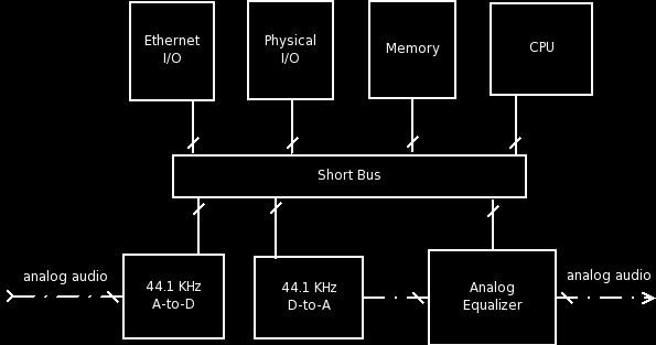
Figure 1. Block diagram of the R.E.T.A.R.D.
II. Audio Processing
As discussed earlier, this device will have eight analog audio inputs and eight analog audio outputs. Six inputs will be stereo headphone jacks, and two will be RCA inputs. The outputs will all be speaker wire. A diagram of the route the audio signals take through the device can be seen in Figure 2. After entering the device, the inputs will go through an analog-to-digital converter, being sampled at 44.1KHz (or possibly 96KHz) with 24 bits of resolution. At this point, an impulse filter (h[kn]) will be applied to the audio. The impulse filter to be used is specified on the control panel of the device, or through an ethernet connection. To do this, the CPU will have to have a buffer of samples from which is will calculate the final h[n]. After this, the volume of the audio signal will be modified by the CPU. Then, the audio signal will be routed to a specific channel of the digital-to-analog converter. Once it is an analog signal, it will pass through a series of filtering circuits that function as the equalizer. The equalizer will be controlled by the CPU.
III. Physical I/O
From a VHDL standpoint, the physical input and output methods of this device may be somewhat irrelevant. However, a full understanding of the device is not possible without knowing the input and output methods. The R.E.T.A.R.D. will, as discussed earlier, have eight audio input and output jacks. More important, though, is the methods by which end users can control the R.E.T.A.R.D. The device will have eight volume controls; one for each output. It will also have eight seperate equalizer controls. Each equalizer control will control the gain of a specific frequencies. These frequencies will be 100Hz, 215Hz, 460Hz, 1KHz, 2.15KHz, 4.6KHz, 10KHz, and 21.5KHz.
The R.E.T.A.R.D will also feature a user-controllable impulse response filter. This impulse response will be of the form h[kn] = [x x x x x x x x], where each x is a user-controlled value. x will be a signed 4-bit integer, giving it possible values between -6 and 7. The constant k is also user-controllable. This is a time constant that determines the length of the filter.
The equation that describes the functioning of the filter h[kn] = [a b c d e f g h] is seen below:
h[k * n] = (a * h[k * n]) + (b * h[k * (n - 1)]) +
(c * h[k * (n - 2)]) + (d * h[k * (n - 3)]) +
(e * h[k * (n - 4)]) + (f * h[k * (n - 5)]) +
(g * h[k * (n - 6)])
|
IV. Ethernet Control
An ethernet jack will also be present on this device, which will be controlled by a separate ethernet controller. The separate controller will be the Ethernet MAC 10/100 Mbps controller, found on OpenCores.org (http://www.opencores.org/projects.cgi/web/ethmac/overview). The CPU will interface with this, decoding and using the data transmitted. It will only respond to UDP requests on a certain port (to be specified) and ICMP PING requests. It will also need to be able to interface correctly with a DHCP server. If none is found, it will try to establish itself with a static IP on the 192.168.0.x network or the 10.0.0.x network. The operation of this is likely to be somewhat CPU intensive. Functions that a user will be able to perform through the ethernet connection include changing volume, changing equalizer settings, changing routing information, and getting information about current system settings.
V. Multiplexing
The R.E.T.A.R.D., as stated in its name, is able to route any audio input to any audio output. For example, if a user wanted to hear the audio from input 0 on outputs 2 and 4, this device would be able to do that. If the user instead wanted to overload their auditory senses, and wanted to hear each input channel on each output (input 0 -> output 0, input 1 -> output 1, etc.), this device would also be able to do that. However, the R.E.T.A.R.D.'s audio multiplexer will not be able to route a null signal (silence) to an output channel. This can instead be accomplished by setting the volume to zero on that individual output channel.
VI. Summary and Concerns
The R.E.T.A.R.D. is meant to be an audio solution for anyone who has more than one audio source in their home and does not want to have to buy an excessive number of speakers to be able to hear them all conveniently. In addition, it provides digital signal processing functionality to modify audio signals. This is useful not only as a cool party toy but also as a learning device for those trying to understand and grasp the fundamentals of digital signal processing. The CPU of this device will be programmed in VHDL, while the analog circuitry will be designed by hand. Theoretically, when finished, this device should be easily creatable for under $100 (including physical I/O components and a case).
However, there will be a number of programming challenges. The first of these is the design of a simple assembly language to write the program that will be stored in memory. This program will not be easy to program, either; it will need to implement ethernet support, physical I/O support, and also be able to perform signal processing functions on eight signals, all while still outputting the processed audio in real-time (at 44.1KHz or 96KHz). Care must be taken when writing the program to see to it that each signal can be processed in the 22.7 microseconds (or 10.4 microseconds if a 96KHz sample rate is used). Another concern is the design of the ethernet controller. This will not be easy by any means. Overall, though, this is a project that could be completed (not without hard work) over the course of the semester.
|
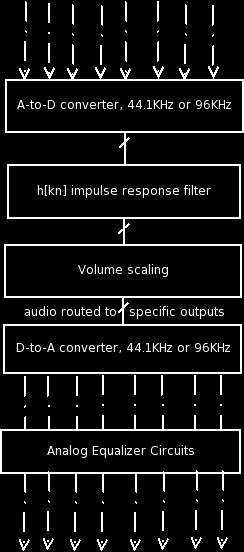
Figure 2. Diagram of the audio signal's path through the R.E.T.A.R.D.
|
|